View DZ Installations in a larger map
Since project inception in 2001, quite a few people installed DZ in their houses. Somehow, I didn't think of visualizing the community until very recently - but now I'm working on rectifying the situation.
Above is the map of known DZ installations, updated with new information as it comes. For all you know, there may be someone next door to you that can help you with the process, should you require assistance.
Saturday, July 31, 2010
Around The World
DZ 3.6 Release Is Out
- Download from SourceForge
- Download from Google Code
- Download from Ohloh
- Get source code from Subversion
- Get the hardware and start enjoying your home
Changes since 3.5.3
New Features

- XBee ZB hardware can now be used to control HVAC actuators. Read more...
- Seed Depot's Relay Shield is supported, along with any other designs that utilize XBee's digital output functionality.
DZ 3.6 Release Is Out
- Download from SourceForge
- Download from Google Code
- Download from Ohloh
- Get source code from Subversion
- Get the hardware and start enjoying your home
Changes since 3.5.3
New Features
- XBee ZB hardware can now be used to control HVAC actuators. Read more...
- Seed Depot's Relay Shield is supported, along with any other designs that utilize XBee's digital output functionality.
Friday, July 30, 2010
Teaser: XBee Wireless Temperature Sensor
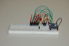
Above: XB24-ZB with four TMP36 analog temperature sensors connected to XBee's analog inputs.
The reason four sensors are connected is: comparison and statistical analysis.
It remains to be seen how good or bad analog readings are, and how easy it is to compensate for these imperfections in software.
Credit
This design is based on a similar one, with a few minor differences:- TMP36 is used instead of LM34 (the only reason being that I had some spares laying around). Obviously, the result calculation is different. Wide selection of similar sensors (TMP35, TMP37, LM35), result would be just about the same, save for value recalculation;
- Incidentally, this allowed to get rid of the voltage regulator because whereas LM34 requires +5V to +30V power, TMP36 is fine from +2.7V to +5.5V, hence, the same 3.3V power can be used to feed both XBee and TMP36;
- Caveat is, at +70°C TMP36 output voltage reaches maximum allowable voltage for ZB series ADC, 1.2V. I don't think it's a problem because the intended usage is indoor temperature measurement, if your indoor temperature reaches +70°C, you'll have bigger problems to worry than a possibly damaged XBee. But keep this in mind if you're planning to use these sensors to monitor a temperature of, say, a water heater or air coming out from the furnace;
- 330Ohm resistor added to ASSOC LED to restrict the LED's operating current (might want to use 1K and higher if your LED is too bright for you).
More to come.
Thursday, July 29, 2010
DZ XBee HOWTO
Now that XBee is supported, let's see how to make it work.
Bill of Materials
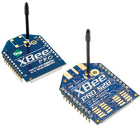
- XBee ZB low power ZigBee Module w/ chip antenna or similar (wire or external antenna, but that would probably be an overkill);
- UartSB V2.2 or similar ("adapter" hereinafter). XBee Explorer Regulated or XBee Explorer USB will also work (WARNING: read the note on SeedStudio products);
- Relay shield (4 relays).
I would highly recommend to buy an extra XBee radio and an adapter if you have never worked with XBees before - it'll save you a lot of grief because you'll be able to monitor the network status activity. You see, the relay shield doesn't come with network status and activity lights, so unfortunately, you'll be flying blind and will have to re-plug XBee modules into adapter every time you're not sure what is going on.
Hence, recommended quantities are - three XBee modules, two adapters and one relay shield (add extra XBee module + relay shield pairs if you have more than one HVAC unit, one pair per unit) - starting at $110.80 before shipping.
Minimum quantities - two XBee modules, one adapter and one relay shield ($73.90 before shipping).
Before you say that's expensive, think how much you will spend breaking walls to wire cables, then patching them back, texturing and painting. Not even talking about time spent on all that exciting work.
Keep in mind that some suppliers have high lead times - I've seen as high as two weeks.
Power
Note that the power supply is not included into the bill of materials. The relay shield requires 9V DC power - you either might have one handy already, buy a cheap one wherever you fancy, or just use a 9V battery (the relay shield has screw on contacts for that). I don't know yet how long the relay shield is going to last on a battery with normal HVAC usage pattern, will find out and report.Setup
Countless XBee tutorials exist, so I'm going to skip this part - suffice to say, get your XBees lined up and talking to each other.
DZ specific XBee setup
You need to flash one XBee module (the one on the adapter) with the Coordinator API firmware (when you get familiar with X-CTU software, this will become self-explanatory). Make sure you read the module configuration and flash correct firmware. After you flash API firmware, it won't be possible to use a dumb terminal to control the XBee anymore (limitation of ZB series), so make sure you're done with setting up communications correctly before you do that - like I said, extra XBee and an adapter will help a lot from here on.IMPORTANT: Make sure you set AP=2 and write changes. The reason for this is that xbee-api library used for low level communications doesn't work with AP=1, and fails to report when AP=1, or forcibly change the module state to AP=2.
Baud Rates
Don't bother changing the port speed from default 9600 baud. DZ is more than happy with that speed, but if you change it, you might run into trouble remembering what it is next time you try to connect to XBee via an adapter.DZ Configuration
XBee devices are configured in exactly the same way as 1-Wire devices: using a device factory. Here's a snippet that will produce a working switch (0013A200.4062AC98 is the 64 bit hardware address of my XBee module plugged into the relay shield, substitute it with yours):<bean id="device_factory" class="net.sf.dz3.device.sensor.impl.xbee.XBeeDeviceFactory" init-method="start"> <constructor-arg index="0" value="/dev/ttyUSB0"/> </bean> <bean id="switch_0013A200.4062AC98_0" factory-bean="device_factory" factory-method="getSwitch"> <constructor-arg value="0013A200.4062AC98:D0"/> </bean>
NOTE: Relays are marked COM1 to COM4, but channels to access them correspond to actual XBee channels - D0 to D3. This is done so that all XBee digital outputs can be controlled - D0 to D8, and P0 to P3.
Congratulations, you're done
From here on, things are just as usual - use the reference to switch_0013A200.4062AC98_0 as you would have with a 1-Wire based device.
UPDATE: Adjusted description to match the improved channel addressing.
UPDATE: This article describes the switch setup, see the Teaser: XBee Wireless Temperature Sensor for information about sensor setup.
Early Access: Going Wireless with XBee
Don't want to break your walls to wire cables? Newsflash: you don't have to anymore.
Subversion contains the driver for XBee ZB based switches (sensor drivers are underway). As usual, if you can read source code and configure a Spring IoC container, you will have no trouble utilizing it. Configuration of an XBee device is just like the configuration of a 1-Wire device (start with the device factory... and so on and so forth).
Subversion contains the driver for XBee ZB based switches (sensor drivers are underway). As usual, if you can read source code and configure a Spring IoC container, you will have no trouble utilizing it. Configuration of an XBee device is just like the configuration of a 1-Wire device (start with the device factory... and so on and so forth).
Hardware
As usual, wide range of devices is supported, but the specific hardware drivers were written on is:
The device connected to the computer must have the Coordinator API firmware with AP=2. Relay shield is equipped with Router AT firmware XBee, but most probably End Device AT firmware will work, too - as well as API firmware of both kinds.
No custom firmware is required on XBee devices.
More to come.
Saturday, July 24, 2010
DZ 3.5.3 Release Is Out
- Download from SourceForge
- Download from Google Code
- Download from Ohloh
- Get source code from Subversion
- Get the hardware and start enjoying your home
This is a maintenance release.
Changes since 3.5.2
Major Bugfixes
- Fixed the issue with 1-Wire device departures breaking the system;
- Fixed the issue with 1-Wire devices being invisible on Aux channel;
- Passed another round of memory leak hunt (found a leak in Java logging framework instead of DZ).
Minor Bugfixes
ServoDamperwill now reverse properly.
New Features
- Added
NullSwitchto allow actuator mocks (as well as using existing HVAC drivers to run less complex devices); - Added
SingleSwitchDevice(experimental); - Added economizer abstraction and simple implementation;
- Added resource usage counter abstractions and simple implementation;
- Started integration with Sonatype Maven repository;
- Added unified connector framework and HTTP connector;
- Verified compatibility with 8CIO8-R1-A 8 Channel I/O (8 Relay Version), should also work with 8CIO4-R1-A 8 Channel I/O (4 Relay Version);
- Verified compatibility with 6CMH1-R3-A 6 Channel Master Hub;
- Added configuration switch to disable damper crawling (for slow serial servo controllers);
- Added configuration switch to enable workaround for deadlocks (happens with some 1-Wire device containers not yet thoroughly tested).
Thursday, July 15, 2010
DZ Temperature Sensor HOWTO
In order to make DZ tick, you need sensors. Preferably lots of sensors. This article will show you how to make them in a very quick, cheap, and quite inconspicuous way.
Bill of Materials
- A DS1820 family sensor (any variant will do: DS18B20, DS18S20, DS1822, DS1920)
- CAT5 RJ-45 connectors, dime a dozen anywhere including your local Fry's
- Bulk CAT5 cable
- Heat shrink tubing
- Marker tape of your choice
Tools
Beyond obvious,
- RJ-45 Crimp Tool
- Heat Gun
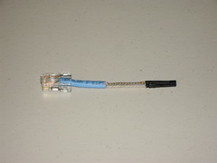
Step 1: Strip & Crimp
Crimp the RJ-45 connector onto the end of a piece of CAT5 cable using T568-B pinout.
Measure 3" from the end of the jack, cut the cable. Measure 2" from the end of the cable, strip the insulation, remove the extra thread.
You can try to cut the cable shorter - the reason I didn't want to do it is I didn't want to risk activating the heat shrink by soldering. YMMV.
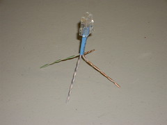
Step 2: cut extra wires
There are two possible choices:
- Make the sensor completely compatible with Hobby Boards wiring scheme (data sheet gone with Hobby Boards sold and website defunct) (careful, they use T568-A and not T56-B);
- Extend wiring in order to provide an ability to create an electrical bus configuration on star physical configuration.
In any case, cut the brown pair and white+orange, you won't need them.
Hobby Boards Pinout
You would want this pinout if you're plugging the sensor directly into a Hobby Boards device, or into a socket that is daisy chained to the next run. Or, if this is the last sensor in the "electrical bus, physical star" configuration.
- White+Blue (pin 5):
GND(see DS1820 data sheet) - Blue (pin 4):
DQ - Orange (pin 2, not pin 6!!!):
Vdd
I left the green pair hanging not to waste the jack, the cable and, most importantly, time spent on crimping, for the case when I'll need to convert this layout into DZ layout (it's pretty simple to cut the heat shrink tubing).
DZ Pinout
You would want this if you're plugging the sensor into a socket that is wired to a patch panel and you want to patch the return to the next run.

- White+Blue, White+Green (pin 5):
GND - Blue + Green (pin 4):
DQ - Orange (pin 2, not pin 6!!!):
Vdd
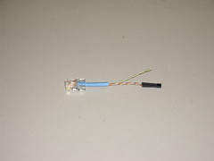
Step 3: Solder and Insulate
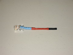
Congratulations, you're done

If you look closely (click to see the big picture), you'll see that cables are marked - blue strip for Hobby Boards pinout, blue and green for DZ pinout.
WARNING: Never plug a DZ sensor into a socket with Hobby Boards pinout!
It may be even SO compatible

The result is not that visible at all, honestly.
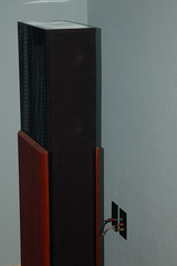
The Missing Link: Where does it go?
So where are all these sensors plugged into? Answer is, RJ-45 sockets wired to a patch panel, which is, in turn, wired to a punchdown block DZ hardware is connected to. But that's a different story for a different time.
<Stay tuned>
Wednesday, July 14, 2010
Ceiling Fans, Caught Red Handed
Remember, I was telling you not to turn them on?
Well, now they've been caught in action - take a look (clickable):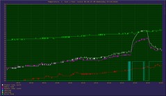
The fan was turned on at 10:29 and turned off at 10:35.
In other words, every time you feel tempted to turn your ceiling fan on, stop and think whether you want the short term relief because of air circulation and long term loss because of extra heat that it generates, or the other way around.
I suggest you just turn the thermostat down a bit.
Tuesday, July 13, 2010
Early Access: Resource Usage Counter
Ever wanted to find out how many hours did your HVAC actually work? Keep forgetting to replace the filter? Well, here's your cure -
Subversion contains the implementation of the resource usage counter. As usual, if you can read source code (FileUsageCounter is probably the one you're looking for) and configure a Spring IoC container, you will have no trouble utilizing it.
Resource usage counters are
DataSinks and can count whatever is DataSource<Double>.Also, they are
DataSource<Double> themselves and can be fed into data loggers - you'll easily see when exactly did your HVAC equipment work.Saturday, July 10, 2010
Thursday, July 8, 2010
Early Access: 1-Wire departures/arrivals
The issue with departing 1-Wire devices breaking the system is fixed. The fix is available from Subversion.
Subscribe to:
Posts (Atom)