In order to make DZ tick, you need sensors. Preferably lots of sensors. This article will show you how to make them in a very quick, cheap, and quite inconspicuous way.
Bill of Materials
- A DS1820 family sensor (any variant will do: DS18B20, DS18S20, DS1822, DS1920)
- CAT5 RJ-45 connectors, dime a dozen anywhere including your local Fry's
- Bulk CAT5 cable
- Heat shrink tubing
- Marker tape of your choice
Tools
Beyond obvious,
- RJ-45 Crimp Tool
- Heat Gun
Step 1: Strip & Crimp
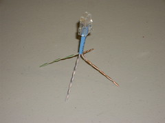
Crimp the RJ-45 connector onto the end of a piece of CAT5 cable using T568-B pinout.
Measure 3" from the end of the jack, cut the cable. Measure 2" from the end of the cable, strip the insulation, remove the extra thread.
You can try to cut the cable shorter - the reason I didn't want to do it is I didn't want to risk activating the heat shrink by soldering. YMMV.
Step 2: cut extra wires
There are two possible choices:
- Make the sensor completely compatible with Hobby Boards wiring scheme (data sheet gone with Hobby Boards sold and website defunct) (careful, they use T568-A and not T56-B);
- Extend wiring in order to provide an ability to create an electrical bus configuration on star physical configuration.
In any case, cut the brown pair and white+orange, you won't need them.
Hobby Boards Pinout
You would want this pinout if you're plugging the sensor directly into a Hobby Boards device, or into a socket that is daisy chained to the next run. Or, if this is the last sensor in the "electrical bus, physical star" configuration.
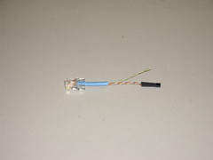
- White+Blue (pin 5):
GND(see DS1820 data sheet) - Blue (pin 4):
DQ - Orange (pin 2, not pin 6!!!):
Vdd
I left the green pair hanging not to waste the jack, the cable and, most importantly, time spent on crimping, for the case when I'll need to convert this layout into DZ layout (it's pretty simple to cut the heat shrink tubing).
DZ Pinout
You would want this if you're plugging the sensor into a socket that is wired to a patch panel and you want to patch the return to the next run.

- White+Blue, White+Green (pin 5):
GND - Blue + Green (pin 4):
DQ - Orange (pin 2, not pin 6!!!):
Vdd
Step 3: Solder and Insulate
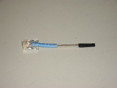
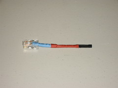
Congratulations, you're done

If you look closely (click to see the big picture), you'll see that cables are marked - blue strip for Hobby Boards pinout, blue and green for DZ pinout.
WARNING: Never plug a DZ sensor into a socket with Hobby Boards pinout!
It may be even SO compatible

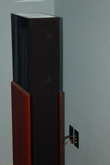
The result is not that visible at all, honestly.
The Missing Link: Where does it go?
So where are all these sensors plugged into? Answer is, RJ-45 sockets wired to a patch panel, which is, in turn, wired to a punchdown block DZ hardware is connected to. But that's a different story for a different time.
<Stay tuned>
No comments:
Post a Comment